Power Your
Future
Licensed electrical & solar experts serving Southern California homeowners and businesses. From panel upgrades to full solar installations — we bring the heat.
Our Services
Electrical Panel Upgrades
200A upgrades, sub-panels, and code-compliant installations for modern homes.
Solar Installation
Full residential solar systems with battery storage, designed for SoCal sun.
Repairs & Troubleshooting
Fast-response diagnostics and repair for outlets, wiring, and circuit issues.
Solar Panel Cleaning
Professional cleaning to remove dirt, debris, and buildup that reduces energy output and panel lifespan.
EV Charger Installation
Level 2 charger installs for Tesla, Ford, and all EV makes and models.
Commercial Electrical
Tenant improvements, lighting retrofits, and commercial power distribution.
Subcontracting Partners
Need expert electricians to fill your pipeline? Electric Diablo provides turnkey subcontracting fulfillment for general contractors, solar companies, and property managers across Southern California.
- Licensed C-10 electricians ready to deploy
- Flexible crew sizing — 1 tech to full teams
- White-label service for your brand
- Warranty-backed workmanship
- Real-time project communication
- Serving LA County & Inland Empire
Why GCs Choose Us
Speed
Same-week crew deployment across SoCal.
Quality
Every job passes inspection first time.
Scale
From single-family to multi-unit developments.
Trust
Fully insured with transparent billing.
Abandoned Projects
Did your previous solar installer go out of business without finishing your project? We can help. Our technicians will conduct a full assessment of the remaining scope of work, diagnose any issues, and get you running on sunshine in no time.

Electric Diablo
Based in Anaheim, Electric Diablo has been powering Southern California homes and businesses with top-tier electrical and solar solutions. Our team of licensed C-10 electricians brings craftsmanship, code compliance, and a relentless commitment to safety on every project.
If you're a homeowner needing a panel upgrade or a general contractor looking for a reliable subcontracting partner, we deliver work that passes inspection the first time — every time.
Where We Work
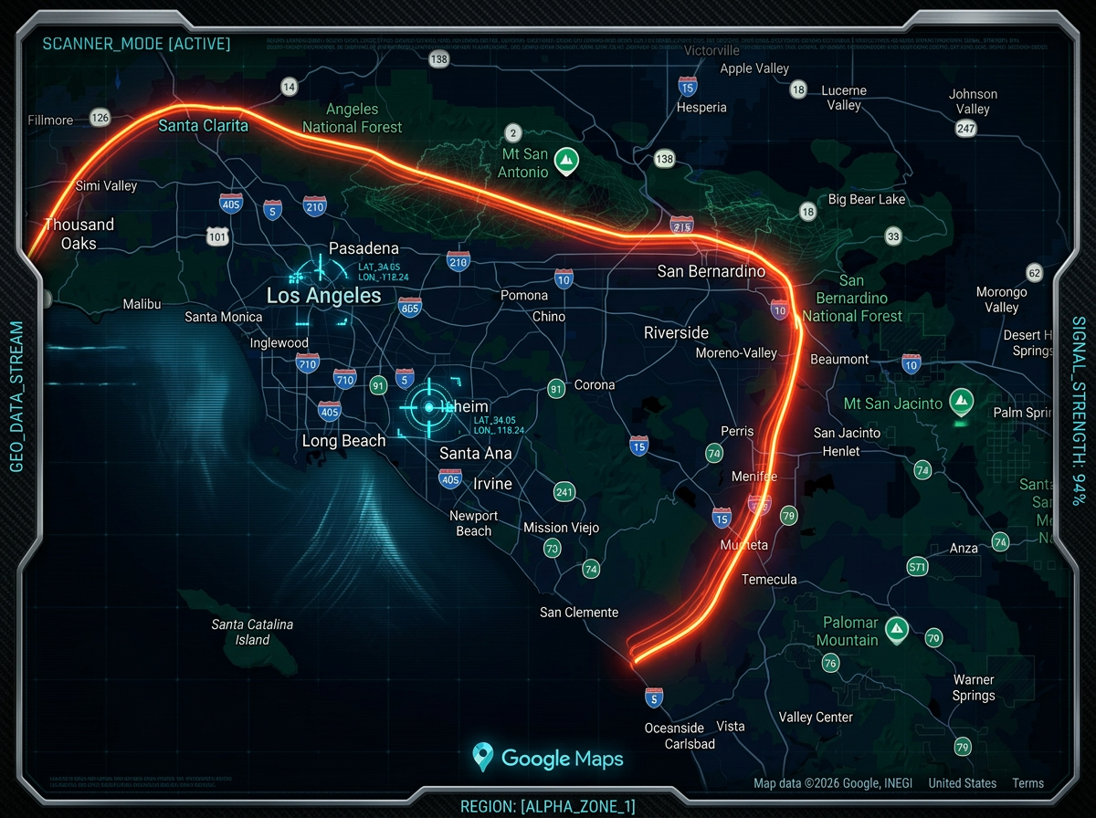
In Southern California but outside these areas? Drop us a line and let's talk about your needs. If you need our help, we can make the drive!
Contact Us
Ready to Get Started?
If you need a residential service call or want to discuss subcontracting partnerships, our team is ready to help. Call us or fill out the form for a free estimate.
Brands We Work With
Trusted partners and suppliers powering our electrical & solar projects across Southern California.